Wednesday 8 May 2024

Tube-a Smarties (Part 4) - the EQ (and the wrap-up)

 So, it was a bit tricky thanks to it being glued in place,  both from components being hidden from view and from hot-melt glue obscuring circuit traces and component values, but I managed to trace the EQ board:


I ended up having to continuity test to find one circuit trace, and to discover that the CW end of the bass pot was disconnected (also, when at zero, the resistance from the CW end to the wiper is a precise and steady 100k ohms, so it was not in a circuit), but a strategically placed gob of glue still concealed the true value of the brown capacitor at far right above-220pF is my best guess.


The traced schematic looks odd, but after hours trying to wrestle the SPICE circuit simulator in KiCad 8 into submission (it's pretty bad-a dumbed-down GUI that depends on KiCad models for a lot of SPICE functions such as sources - come back LTSpice, all is forgiven) I worked out that this is actually a functional circuit design, taking into account the 220nF input cap from the main board and the 470k output load to ground on the main board. The midband is centred about 365 Hz and can attenuate by a range of about 24 dB. I believe the EQ (really a tone control) attenuates about 7dB with controls at maximum, which is close to the attenuation from the bypass circuit.

The only gripes are pretty minor ones-design best practice would have been to connect the floating pin 3 of RV3 to the wiper to mitigate pot rotation noise, and the multiple ground connections on the ribbon cable header really should be matched at the main board but aren't (see Part 3).

Just to wrap up, this pedal seems to have earned a permanent spot between the bass and my amp. It sounds that good. And here is the only remaining information about or mention of the pedal on the internet - in the Wayback Machine. 

Monday 6 May 2024

Tube-a Smarties (Part 3) - the analysis

 (read Part 1 and Part 2 if you haven't already) 

So, I've managed to trace the schematic for the main board, and it's, well, interesting...


Like most valve gear, it's pretty elegant (you had to be parsimonious with those bulky, hot, expensive glass bulbs).  The way it all works is that a negative voltage between the grid (G) and the cathode (K) will progressively cutoff the current flowing through the valve, so that a small voltage signal applied to the grid will create a voltage across the resistors connected to the cathode (K) and Anode (A), and if the voltage across the anode and cathode is large enough, the response is sorta linear. Cue the joys of the small signal model! The voltage drop across the 1.8k resistors at the cathodes "biases" them slightly above 0 volts (about 1.4V). Therefore,  0V at the grid is slightly negative by comparison to the cathode, and as a consequence small audio signals centred around 0V at the grids will stay in the valve's linear region and not distort *too* badly.

As I predicted in part 1, it has a diode bridge and a classic pi filter to deliver a nice smooth high voltage to the plate supplies (B supply in the US of A, HT supply in Blighty). However, the circuitry around the 6.3VAC valve heater is a bit odd.

Firstly, it has a couple of resistors which seem to have the goal of providing a path to ground for both sides of the heater. If the goal was to provide a ballast load to prevent the transformer putting too much voltage into the valve, then a 1k resistor across the AC terminals would have done the same job. However, it appears that this is a tried-and-true technique for reducing hum radiation from the heater into the valve's outputs.

Secondly, the LED circuit is confusing. Using a diode to protect the LED is best-practice engineering, as LEDs do not like reverse voltages. Obviously an intent was to reduce AC flicker (the designer probably had a customer whine that looking at the LED gave them migraines), but the approach of using a capacitor to mitigate flicker seems all wrong-it should charge through a 10 ohm resistor and discharge into the capacitor through the 470 ohm resistor, not the other way around. 

Also, having a second LED series resistor seems pointless - until you realise this guy obviously liked using 10 ohm resistors as cheap wire link bridges on the circuit board-see V1A's grid resistors, where the second 10 ohm grid resistor is well within the tolerance range of the 47k resistor so it is practically useless. Likewise, the two 4k7 resistors on the output could easily have been replaced with a single 10k one.

Thirdly, while the tightly twisted pairs for the AC supplies and audio in/out to the main board are good design practice, using a ribbon connector without ground-connected lines inbetween the signal wires is not. The unused lines in the ribbon could have easily been connected to ground.

Finally, the fixed 1 Megohm resistor in the output circuitry serves a valid purpose-protecting the output from footswitch noise by ensuring a DC path to ground while the switch is changing over. Likewise the 100k resistor that bridges the input jack when it has nothing plugged in prevents hum and noise pickup.


Sunday 5 May 2024

Tube-a Smarties (Part 2) - under the hood

(read Part 1 if you haven't already) 

So, I managed to have a look at the circuit board yesterday. Only one of the screws holding the main PCB required pliers to extract it-as a result of some rust at the end of it.

The other side:


Pretty much as I expected from the other side. BAC1 and BAC2 are 47uF 350V types, textbook plate voltage filter cap values. Interesting to note that the circuit ground is isolated from the chassis by a 10 ohm resistor for noise isolation plus a diode pair as a safety switch in case signal ground goes "live" to a voltage over 0.5 volts. The huge red capacitor is a 220nF 400V DC blocking capacitor to couple the passive EQ board to the high-voltage plate of one of the valve amplifiers sections. Lastly, the "unbypassable" output DC coupling resistor is 1Mohm, so it should not affect "muh toan" too badly.

Looking under the can, we find this:


A Groove Tubes 12AX7, so a decent brand for the time, and from an era before Metasonix introduced adventurous valve choice to guitar pedals and amps. At this point people were overwhelmingly still just using the same four or five valve types that Leo Fender or Vox had used in 1960 to design guitar amps.

As mentioned before - safety...one can say this is the product of a more innocent time, but even then people would put fibre insulator cards between a circuit board with exposed 200 volt solder points and a metal case that is less than a centimetre away. This guy didn't. While I'm sure it is safe, I would not use this at a gig where there might be drink spills...

Part 3 coming soon!

Tube-a Smarties (Part 1) - the discovery

 Amazing what you can still find in a hock shop in an era when everything (including secondhand gear) has been getting expensive. I went into a local pawn shop to see this peeking through a pile of stuff in the shop window...

Lab Systems VPF-1 Truetube pedal


I figured given the captive mains lead it actually was based around valve technology, and the cheesy typography on the panel either signified an "AliExpress Special" Chinese product (think early Donner), or an actual boutique manufacturer run by an engineer with questionable graphics design skills. (As an aside, engineers should not be allowed near the Bauhaus font - ever!)

Trying to find a reference to it, there is literally nothing in the current WWW, and Google turned up a complete blank. I could find out that Lab Systems were a well regarded maker of bass amplification in Melbourne the 1980s and 1990s, but ceased trading in the 00s, and while there are some (very folksy) manuals for some of their gear preserved on the web, this wasn't one of them.

Needless to say I was there the next morning, $A75 (about $50 in Freedom Fries currency) in hand-and then the retailer's credit card machine managed to crap the bed and eject its entire roll of thermal paper rather than complete the sale. One instant bank transfer later, however, and this machine was mine!!!!

Lab Systems VPF-1 Truetube pedal

On plugging it in, the power indicator/footswitch status LED turned on, nothing emitted burning smells, and no circuit breakers tripped, so once I got it home it was time for a look under the hood.


Well, that's definitely a valve poking out from under the circuit board, and some sort of passive EQ circuit on the hot-glued daughter card. The somewhat dodgily screwed-in little transformer has 6.3VAC and 200VAC secondaries, so unlike most modern gear, it seems to run the valve at full rated heater power AND a decent plate voltage (As an aside, the requirement to get expensive electricity authority approval for every country you sell equipment that runs over 50V inside the case has compromised the design of a lot of valve gear, but electricity authority approval or indeed safety was not on our old mate the engineer's radar, as we shall see later).

Looking more closely at the back of the single-sided main circuit board, nicely retained with shake-proof washers and Loctite retention glue for the screws, we can work out a few things going on even without seeing the other side:


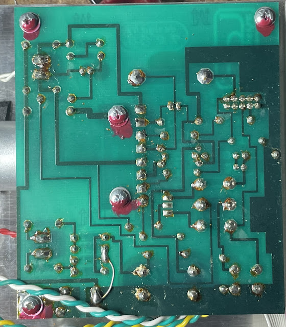
At the bottom, the red 200VAC wires are almost certainly feeding in through resistors to a full-rectifier diode bridge (where the link/bodge wire is), which then goes to a big-ass capacitor to ground (let's call it BAC1), which then feeds via a resistor to BAC2, and then to a couple of plate resistors (the valve evidently contains two independent amplifiers). This configuration was called a Pi filter (because in circuit diagrams it looks like a Pi symbol with two capacitor legs to ground and a resistor or inductor bridging them on top) and is a classic way of filtering mains hum out of the plate voltage for valve supplies. Indeed, after the unit was turned off, BAC1 still had enough charge to arc my screwdriver when I touched it across the contacts. With power on, I measured 279VDC across BAC1, 271V DC across BAC2 (due to the "Pi" resistor dropping voltage) and 190V at the closest valve plate. 

Another thing-the "Pure Valve" appellation is truth in advertising-the only silicon in the whole thing is supply rectifier diodes and the indicator LED. All buffering and amplification in the audio path is done by the valve, and the audio does not pass through any solid-state semiconductors!

At top, the 6.3VAC supply (white wires) is fed directly to the valve heater, and also powers the status LED via a ballast resistor. Whenever the pedal has a "cold start", the LED takes a couple of seconds to reach peak brightness. This would be because the initial inrush current (due to the valve's heater having a low "cold resistance") is causing the dinky transformer to "regulate" and drop its output voltage until the heater warms up - which would have the benefit of soft-starting the valve, thereby prolonging its life.

At bottom left, one of the retention screws connects the circuit ground to the case (which is wired directly to mains earth), but via what appears to be a resistor-or three?

Lastly, it has a mechanical switch bypass which connects the input to the output, but does not bypass the ground-coupling resistor on the output, nor does it disconnect the input from the passive equaliser daughterboard, so not "true bypass". Sorry, cork-sniffers.

So does it work, and does it justify the 75 bucks? Yes and yes.

Plugging my MTD Kingston Heir bass into it, I found it can deliver a nice clean boost (with a small bit of plate noise only noticeable if you're really looking for it, and no discernible hum), plus the EQ is subtle but musically useful.

Part 2 coming soon!!!


Tube-a Smarties (Part 4) - the EQ (and the wrap-up)

 So, it was a bit tricky thanks to it being glued in place,  both from components being hidden from view and from hot-melt glue obscuring ci...