Saturday, 8 June 2024

A simple diversion..

 I've decided to launch a side-blog to document my experiences modernising vintage open-source DIY synth designs, cos why not? Fear not, I will still be maintaining this one in parallel.

Check out Electromutations!

Wednesday, 8 May 2024

Tube-a Smarties (Part 4) - the EQ (and the wrap-up)

 So, it was a bit tricky thanks to it being glued in place,  both from components being hidden from view and from hot-melt glue obscuring circuit traces and component values, but I managed to trace the EQ board:


I ended up having to continuity test to find one circuit trace, and to discover that the CW end of the bass pot was disconnected (also, when at zero, the resistance from the CW end to the wiper is a precise and steady 100k ohms, so it was not in a circuit), but a strategically placed gob of glue still concealed the true value of the brown capacitor at far right above-220pF is my best guess.


The traced schematic looks odd, but after hours trying to wrestle the SPICE circuit simulator in KiCad 8 into submission (it's pretty bad-a dumbed-down GUI that depends on KiCad models for a lot of SPICE functions such as sources - come back LTSpice, all is forgiven) I worked out that this is actually a functional circuit design, taking into account the 220nF input cap from the main board and the 470k output load to ground on the main board. The midband is centred about 365 Hz and can attenuate by a range of about 24 dB. I believe the EQ (really a tone control) attenuates about 7dB with controls at maximum, which is close to the attenuation from the bypass circuit.

The only gripes are pretty minor ones-design best practice would have been to connect the floating pin 3 of RV3 to the wiper to mitigate pot rotation noise, and the multiple ground connections on the ribbon cable header really should be matched at the main board but aren't (see Part 3).

Just to wrap up, this pedal seems to have earned a permanent spot between the bass and my amp. It sounds that good. And here is the only remaining information about or mention of the pedal on the internet - in the Wayback Machine. 

Monday, 6 May 2024

Tube-a Smarties (Part 3) - the analysis

 (read Part 1 and Part 2 if you haven't already) 

So, I've managed to trace the schematic for the main board, and it's, well, interesting...


Like most valve gear, it's pretty elegant (you had to be parsimonious with those bulky, hot, expensive glass bulbs).  The way it all works is that a negative voltage between the grid (G) and the cathode (K) will progressively cutoff the current flowing through the valve, so that a small voltage signal applied to the grid will create a voltage across the resistors connected to the cathode (K) and Anode (A), and if the voltage across the anode and cathode is large enough, the response is sorta linear. Cue the joys of the small signal model! The voltage drop across the 1.8k resistors at the cathodes "biases" them slightly above 0 volts (about 1.4V). Therefore,  0V at the grid is slightly negative by comparison to the cathode, and as a consequence small audio signals centred around 0V at the grids will stay in the valve's linear region and not distort *too* badly.

As I predicted in part 1, it has a diode bridge and a classic pi filter to deliver a nice smooth high voltage to the plate supplies (B supply in the US of A, HT supply in Blighty). However, the circuitry around the 6.3VAC valve heater is a bit odd.

Firstly, it has a couple of resistors which seem to have the goal of providing a path to ground for both sides of the heater. If the goal was to provide a ballast load to prevent the transformer putting too much voltage into the valve, then a 1k resistor across the AC terminals would have done the same job. However, it appears that this is a tried-and-true technique for reducing hum radiation from the heater into the valve's outputs.

Secondly, the LED circuit is confusing. Using a diode to protect the LED is best-practice engineering, as LEDs do not like reverse voltages. Obviously an intent was to reduce AC flicker (the designer probably had a customer whine that looking at the LED gave them migraines), but the approach of using a capacitor to mitigate flicker seems all wrong-it should charge through a 10 ohm resistor and discharge into the capacitor through the 470 ohm resistor, not the other way around. 

Also, having a second LED series resistor seems pointless - until you realise this guy obviously liked using 10 ohm resistors as cheap wire link bridges on the circuit board-see V1A's grid resistors, where the second 10 ohm grid resistor is well within the tolerance range of the 47k resistor so it is practically useless. Likewise, the two 4k7 resistors on the output could easily have been replaced with a single 10k one.

Thirdly, while the tightly twisted pairs for the AC supplies and audio in/out to the main board are good design practice, using a ribbon connector without ground-connected lines inbetween the signal wires is not. The unused lines in the ribbon could have easily been connected to ground.

Finally, the fixed 1 Megohm resistor in the output circuitry serves a valid purpose-protecting the output from footswitch noise by ensuring a DC path to ground while the switch is changing over. Likewise the 100k resistor that bridges the input jack when it has nothing plugged in prevents hum and noise pickup.


Sunday, 5 May 2024

Tube-a Smarties (Part 2) - under the hood

(read Part 1 if you haven't already) 

So, I managed to have a look at the circuit board yesterday. Only one of the screws holding the main PCB required pliers to extract it-as a result of some rust at the end of it.

The other side:


Pretty much as I expected from the other side. BAC1 and BAC2 are 47uF 350V types, textbook plate voltage filter cap values. Interesting to note that the circuit ground is isolated from the chassis by a 10 ohm resistor for noise isolation plus a diode pair as a safety switch in case signal ground goes "live" to a voltage over 0.5 volts. The huge red capacitor is a 220nF 400V DC blocking capacitor to couple the passive EQ board to the high-voltage plate of one of the valve amplifiers sections. Lastly, the "unbypassable" output DC coupling resistor is 1Mohm, so it should not affect "muh toan" too badly.

Looking under the can, we find this:


A Groove Tubes 12AX7, so a decent brand for the time, and from an era before Metasonix introduced adventurous valve choice to guitar pedals and amps. At this point people were overwhelmingly still just using the same four or five valve types that Leo Fender or Vox had used in 1960 to design guitar amps.

As mentioned before - safety...one can say this is the product of a more innocent time, but even then people would put fibre insulator cards between a circuit board with exposed 200 volt solder points and a metal case that is less than a centimetre away. This guy didn't. While I'm sure it is safe, I would not use this at a gig where there might be drink spills...

Part 3 coming soon!

Tube-a Smarties (Part 1) - the discovery

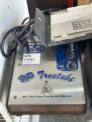
 Amazing what you can still find in a hock shop in an era when everything (including secondhand gear) has been getting expensive. I went into a local pawn shop to see this peeking through a pile of stuff in the shop window...

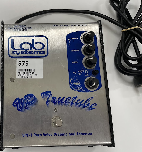
Lab Systems VPF-1 Truetube pedal


I figured given the captive mains lead it actually was based around valve technology, and the cheesy typography on the panel either signified an "AliExpress Special" Chinese product (think early Donner), or an actual boutique manufacturer run by an engineer with questionable graphics design skills. (As an aside, engineers should not be allowed near the Bauhaus font - ever!)

Trying to find a reference to it, there is literally nothing in the current WWW, and Google turned up a complete blank. I could find out that Lab Systems were a well regarded maker of bass amplification in Melbourne the 1980s and 1990s, but ceased trading in the 00s, and while there are some (very folksy) manuals for some of their gear preserved on the web, this wasn't one of them.

Needless to say I was there the next morning, $A75 (about $50 in Freedom Fries currency) in hand-and then the retailer's credit card machine managed to crap the bed and eject its entire roll of thermal paper rather than complete the sale. One instant bank transfer later, however, and this machine was mine!!!!

Lab Systems VPF-1 Truetube pedal

On plugging it in, the power indicator/footswitch status LED turned on, nothing emitted burning smells, and no circuit breakers tripped, so once I got it home it was time for a look under the hood.


Well, that's definitely a valve poking out from under the circuit board, and some sort of passive EQ circuit on the hot-glued daughter card. The somewhat dodgily screwed-in little transformer has 6.3VAC and 200VAC secondaries, so unlike most modern gear, it seems to run the valve at full rated heater power AND a decent plate voltage (As an aside, the requirement to get expensive electricity authority approval for every country you sell equipment that runs over 50V inside the case has compromised the design of a lot of valve gear, but electricity authority approval or indeed safety was not on our old mate the engineer's radar, as we shall see later).

Looking more closely at the back of the single-sided main circuit board, nicely retained with shake-proof washers and Loctite retention glue for the screws, we can work out a few things going on even without seeing the other side:


At the bottom, the red 200VAC wires are almost certainly feeding in through resistors to a full-rectifier diode bridge (where the link/bodge wire is), which then goes to a big-ass capacitor to ground (let's call it BAC1), which then feeds via a resistor to BAC2, and then to a couple of plate resistors (the valve evidently contains two independent amplifiers). This configuration was called a Pi filter (because in circuit diagrams it looks like a Pi symbol with two capacitor legs to ground and a resistor or inductor bridging them on top) and is a classic way of filtering mains hum out of the plate voltage for valve supplies. Indeed, after the unit was turned off, BAC1 still had enough charge to arc my screwdriver when I touched it across the contacts. With power on, I measured 279VDC across BAC1, 271V DC across BAC2 (due to the "Pi" resistor dropping voltage) and 190V at the closest valve plate. 

Another thing-the "Pure Valve" appellation is truth in advertising-the only silicon in the whole thing is supply rectifier diodes and the indicator LED. All buffering and amplification in the audio path is done by the valve, and the audio does not pass through any solid-state semiconductors!

At top, the 6.3VAC supply (white wires) is fed directly to the valve heater, and also powers the status LED via a ballast resistor. Whenever the pedal has a "cold start", the LED takes a couple of seconds to reach peak brightness. This would be because the initial inrush current (due to the valve's heater having a low "cold resistance") is causing the dinky transformer to "regulate" and drop its output voltage until the heater warms up - which would have the benefit of soft-starting the valve, thereby prolonging its life.

At bottom left, one of the retention screws connects the circuit ground to the case (which is wired directly to mains earth), but via what appears to be a resistor-or three?

Lastly, it has a mechanical switch bypass which connects the input to the output, but does not bypass the ground-coupling resistor on the output, nor does it disconnect the input from the passive equaliser daughterboard, so not "true bypass". Sorry, cork-sniffers.

So does it work, and does it justify the 75 bucks? Yes and yes.

Plugging my MTD Kingston Heir bass into it, I found it can deliver a nice clean boost (with a small bit of plate noise only noticeable if you're really looking for it, and no discernible hum), plus the EQ is subtle but musically useful.

Part 2 coming soon!!!


Saturday, 29 October 2022

Cat in a Can

 I had a rough start to the working week last week, so a bit of retail therapy was in order. Going to my favourite hock shop I saw this with a $299 price tag. A piece of 1973 ancient history/juvenilia from one of the most iconic synth makers of all time; a bizarre unique design (and nomenclature); a very good price; and a cool FX pedal to boot? Hell yes!


It did not disappoint. The Funny Cat AG-5 is a unique design that has an "SDS" distortion, (over) drive section switched in and out on the right, and a rather unique envelope filter ("Harmonic Mover") switched on the left that, on at least one of its three settings, has an attack that is just like a cat's meow (hence the name). It was a contemporary of the similarly oddly named, but now highly sought after, Bee Baa two stage fuzz pedal, that sells for even more that this little guy (which itself has an indicative sold price hovering around $500 AUD on Reverb).

The physical design is pure 1973, a solid sheet steel enclosure that takes up a fair chunk of space, mechanical foot switches, battery operation only, and controls out of harms way and out of sight/out of mind of the guitarist - all on the back (audience) side of the unit.


Controls are straightforward - an output level adjust for the SDS, a mix control between the Harmonic Mover output and whatever goes into it from the SDS footswitch, and three envelope responses for the Harmonic mover. In keeping with the time it was made, the circuit is buffered at all times and has a rather low input impedance - true bypass loving tone questers look elsewhere!

I tested it with my Yamaha active pickup bass, and it could range from hard to tame, with the Harmonic Mover ranging from nasty-in-a-good-way (on the fastest envelope setting) to remarkably musical on the more docile setting. The crazy filter circuit (a transistor warping an RC circuit) has a unique character.

The unit opens up easily-there are four thumbscrews on the side, two of which serve as a hinge for the bottom plate when loose, and two that can swing out of the body.


The insides look just how they would have in 1973-note the green stuff around the screws, jacks and pots - this would be Loctite adhesive or similar, that has done a stellar job of holding everything together for half a century, despite the beating the outside case has taken. The cleanliness of the inside is also a tribute to the  well-sealed enclosure, and the little steel box for the battery is a nice touch. Note also the "blind hole" between two of the pots-there is another between the footswitches under the circuit board. The case was common to the Bee Baa, which had an extra pot and footswitch. 

Check out the copper patches on the circuit board-the rest is silver because it would have been soldered in a "solder bath", but these areas would have been masked off with Kapton tape or the like to keep solder out so parts could be attached later. Hmmm, let's have a look to see what they are...


So why does it have three little circuit boards sticking out, when they could have been put onto a single bigger card? To answer this, we have to consider how things were in audio electronics in 1973. 

A few years before, largely due to the genius of Bob Widlar, the monolithic (ie "chip") operational amplifier (opamp) had revolutionised electronics. A compact, accurate, versatile amplifier was now something that could make electronic design easy, rather than using traditional cascaded transistor based circuits with complex assembly due to lots of parts. 

Problem was, these new little wonders were expensive. Even the uA741, which is remembered now as middling at best, cost about $5 US each in 1971, and for a cost conscious Japanese guitar pedal builder this was probably a deal-breaker. 

At the time there was an alternative used in high-end mixing consoles due to the limited gain-bandwidth performance of early IC opamps, which limited their ability to amplify weak signals such as microphones while keeping the full audio spectrum intact. Companies like Neve and API made opamps from "discrete" parts (ie old-fashioned transistors and resistors) on a little submodule, and these are still made today by and for recording equipment purists, despite ICs having long-since caught up.

So what did Roland do? Unlike the Bee Baa, which has the old-fashioned cascading transistor technology, the Funny Cat was based around the new opamp tech but used cheap-and-cheerful roll-your-own opamp modules. As transistor matching is important for opamps, it is my guess that individual modules needed to be quality tested for performance before they could be soldered in. 

There are good transcriptions of the main Funny Cat circuit around, and people have managed to sell clone PCBs of it, but the clones all use IC opamps which will not have the organic imperfections of the original. I believe this is so because the opamp modules do not appear to have ever been documented. Well, a fun Saturday evening later, that is no longer the case...


The circuit is very simple (though not as simple as, say, the Moog Modular CP3 opamp circuit). It is designed for low power usage and single supply operation, with a Class A output (no crossover distortion, unlike classic 1970s low voltage opamps such as the LM324 or LM358). Also, Roland made life more complex for themselves by putting the negative feedback resistor, usually an external component, on the opamp card. This means that the Funny Cat requires two different card types with different feedback resistors. It seems that Roland didn't trust the circuit to be stable with the feedback resistor on the "motherboard" and wanted to keep it very close to the transistors it bridged.

Anyhow, there goes a first look at a true original from Roland. While I love it, I have a feeling that some of the out-of-control behaviour with the Harmonic Mover is due to a dried-out low-range envelope capacitor - watch this space!


Saturday, 1 January 2022

BBD and me, and Ali Express fakery

In my previous post about the Roland stringers, I mentioned that they all used the Reticon SAD512D chip, but the second iterations of all these designs (circa 1980) switched over to Panasonic chipsets. I thought I would mention a bit about why this happened, and why a dead SAD chip make you, well, sad.

Reticon was actually an early pioneer in the use of CCDs, both in BBD (Bucket Brigade)delays and video sensors. Although co-founder Gene Weckler wasn't part of the Traitorous Eight who left Shockley and co-founded Fairchild, he followed a similar path, working for Shockley straight out of university, then Fairchild, then onto his own startup in 1969.

Their products included the SAD (Sampled Analog Delay) chips, including the SAD1024 with two independent 512 stage delay units, and the SAD512 which was basically a SAD1024 where one half of the chip had failed testing (a 1000-transistor chip in the early 70s would have been a biggish deal to produce in quantity and yields would not have been great). To understand how these worked, one cannot think of them like a digital memory chip, or even a digital delay line like the Princeton PT2399 (their distant descendant), where every location can be in use simultaneously. 

The reason these were called Bucket Brigade was that they consisted of a line of capacitors and electronic switches connected to each other. As a voltage came into the chip at one end it was progressively passed through the entire chip, but instead of being done so in a ripple arrangement, where one voltage is passed out and each other voltage shuffles forward one by one, half the storage locations would be empty at any given time, and each next cycle would either sample an incoming signal and shuffle existing locations forward by one, or output a delayed voltage and shuffle existing locations forward. This may seem inefficient, but it removed the need for complex circuitry to address each delay location individually, as well as ensuring that all locations moved forward simultaneously within a single clock cycle. Indeed, all one had to do was connect the gates of half the bucket transistors to a clock input, and the gates of half the bucket switches to another, and send alternating signals to each clock input. 

What the SAD512D did was no longer make the 512-stage version of the delay line an afterthought, but shrink it down into a compact 8-pin package. It also included some circuitry to generate the alternating clocks from a single square-wave input, thus making the chip very guitar pedal-friendly. 

So sunshine and roses, right? Well, in 1977 EG&G bought Reticon, and it appears they really wanted them for their optoelectronic tech as all further refinement of the SAD BBDs seems to have ceased. Enter Panasonic, who soon developed rival products and continued refining their performance and voltage requirements, and by 1980 had convinced Roland to switch over to their products, even though the Panasonic MN series BBDs always required two external alternating clocks. Before too long both the SAD and Panasonic MN chips were discontinued in the face of digital tech, and became very expensive on the aftermarket. Eventually Uli Behringer's CoolAudio reissued the MN series chips, leaving the SADs high and dry and consigned to history's dustbin. What did not help either is that the SAD chips have a reputation for dying (ie my RS09) and this has further constrained supply and made second-hand parts suspect.

However.....

It appears that SAD512Ds are available again-not officially of course. The Chinese semiconductor market can be a wildwest of recycled scrap parts, sometimes labelled to be that what they are not, or even non-working chips which have been labelled to con desperate and gullible Westerners. Worse still are US Ebay sellers who import this junk and resell it offering it an air of legitimacy at a higher price. Still...when used SAD512D chips that are probably on their way out fetch triple-figure prices, it's tempting...


And indeed I was tempted. So after spending $A15 on AliExpress, this arrived...


The total lack of antistatic packaging was not promising.


And no mistaking the engraved printing for a new-old-stock 1980s manufacture (ink printed) chip. Still, testing time!!!! First up the testing rig:


Followed by removing the precious original from the pedal board for safe storage (after disconnecting the battery)


Then the unknown chip in circuit.


Results: both chips were non-functional. As static damage to both chips in transit is unlikely, one can only assume they were duds to begin with. Lesson learned. On to the repair!


A simple diversion..

 I've decided to launch a side-blog to document my experiences modernising vintage open-source DIY synth designs, cos why not? Fear not,...